Monday 31 December 2012


MY TRAINING VESSEL (DREDGER)


This is my training vessel TSHD NAVAYUGA  in CHENNAI.


Tuesday 11 December 2012


A Day in the Life of a Fourth Engineer

                 No, my dear readers. It’s not easy. Out at sea every day is something different. Something enjoyable and something strange. But each day is unique in its own sense.  This is one such day. A day in the life of a fourth engineer on ship.


0600 hrs.:

The phone rings annoyingly nonstop, until I realized I have to stop it from waking me up especially when I was dreaming of my sign-off date.
I check out the porthole to make sure if its 6 AM or 6 PM. Still dark! It’s been a month since I lost track of that.
I pick up the phone. “Wake up call, sir.” says my motorman.
“Thanks Dan” and I wearily start brushing my teeth and put on my boiler suit.


0700 hrs.:

Reach the engine room and greet the junior and the motorman.
Signal the kid to take a round of the engine room and the daily MARPOL tank soundings.
Time for some nice tea!


0730 hrs.:

After my daily cup of gluttony, I get down to business. Time to take one complete round of the engine room. After all, the responsibility of overseeing $20m + assets is quite something.
“Dan, quite a lot has accumulated in the bilges. Time to transfer it out.”
Dan gives me his “will-do-sir” look and heads off to do the job.


0800 hrs:

Grasping an air of relief, I sat down at the table and realised it was time for my bunker calculations. When the Chief Engineer comes down, he is going to get on to the bunker papers immediately.
Just then the chief enters the engine room. Speak of the devil! I get him to listen to how I am going to accommodate the bunkers in how many tanks and after some healthy inattention I get a response, “Sure V. We can do that”
With a huge relief that I don’t have to redo my plans, I sit down.
580 tonnes, which means that at least a million dollars’ worth of oil. I better be careful.


0900 hrs.:

Something terribly wrong with the purifier.
Second engineer says that he wasn’t able to change the oil to different density yesterday. I immediately realized the problem and decide to open up the machine for overhaul.


1200 hrs.:

After three hours of hard work, the purifier is back and running again.
Feeling good I head up to the cabin only to find the chief waiting there to thank me for a good job. Oh man! Just when I was aching to get some rest.
Invites me into his cabin for a drink. Oh well, a little socializing never hurt anyone.


1300 hrs.:

After an hour of testosterone-charged talking, I return to cabin to prepare my bunker papers. Got a long day ahead.


1400 hrs.:

Doze off without realizing it…


1600 hrs.

*tring tring*Bunker barge is here! Shoot!
Check all the papers are in ship shape. Prepare Gas testing equipments. Go! Go! GO!
Feeling very close to a NFL quarterback, I run back and forth, trying to get the Fitter and the Motormen to connect the hoses and scream a few ear-full at the junior to make himself useful. A Little tough love!


1700 hrs.:

Chief asks me to go to the barge and get the soundings of their tanks.
Gulp! Iced deck and slippery cold railings notwithstanding, I stare threateningly at the 50 knots blowing wind.
An hour’s analysis of whether it’s safe or not to get to the barge takes place.
“I will go”, finally I decide to make the decision making process easy. Can’t be that frightening, can it?
After a 10 m descent to the barge, I get to the Russian manned barge with a dog the size of a young cow. Thankfully, the barge master seems impressed by my bits and pieces of Russian and didn’t let his dog loose on me. Whew!


1800 hrs:

Finally the paperwork and the formalities are done.
“Koroshan”, I yell out to the barge Captain in Russian, meaning “All is good”
Bunker commenced! A million dollar worth of liquid black gold transferred over high seas and I am responsible for it!


2100 hrs.

Alas the bunker is over and round 2 on NFL quarterback running around has commenced.
Papers, papers and lamer Russian speaking continue to reign supreme.


2200 hrs:

Barge is finally ready for cast off. All’s well that ends well, I guess.
Chief seems pretty happy, but still a bit annoyed at receiving a ton of oil less.
“Relax chief. I will make up for it”, I promise and get on to cast off the barge with the junior.
“There you are! Want to head to the city to grab a drink after this??” the second officer quips in from the deck, as we are casting the barge off. Pretending to contemplate an answer for that one, I thoughtfully answer her with a smile” Thought you’d never ask! “ :D

Oh! The Life of a sailor! Keep reading the blog for similar articles......................

Sunday 2 December 2012


Troubleshooting Centrifugal Pumps

                    Because most of the pumps on board ship are centrifugal pumps, we will examine the symptoms and common causes of centrifugal pump problems here.
Centrifugal pumps work, as the name suggests, on the centrifugal forces acting on the liquid being pumped.  

The centrifugal force is imparted to the liquid through the high-speed rotation of a specially shaped impeller.
Whenever we find a centrifugal pump not performing well, the causes can usually be traced back to 3 common reasons:
  • Suction related problem
  • System related problem
  • Mechanical related problem
Now you can easily pinpoint the trouble. Download free DiagnoPump, the pump troubleshooter software Here.


Suction Related Problem

The liquid inside the impeller must behave like a solid column in order for the centrifugal pump to work. More liquid must replace whatever liquid forced out by centrifugal force. If the solid column of liquid is broken, by the presence of air, the pumping effect is reduced or broken, and the pump does not perform properly. Some of the common suction related faults are:
  • Pump not primed
  • Pump suction pipe not completely filled with liquid
  • Suction lift too high
  • Insufficient margin between suction pressure and vapor pressure
  • Excessive amount of air or gas in the liquid
  • Air pockets in the suction line
  • Air leaks into the suction line
  • Air leaks into the pump through the stuffing box or gland
  • Foot valve too small
  • Foot valve partially clogged
  • Inlet of suction pipe insufficiently submerged
  • Water seal pipe plugged
  • Seal cage improperly located in stuffing box, preventing sealing fluid entering space to form a seal

System Related Problem


Most of the system related problems occur because of design flaw. For example, the designer may have chosen the wrong pump whose characteristic does not match the system requirement. For the Marine Engineer working on board ship, these problems are rare. Perhaps sometimes, when replacing motors, and starting up. Below are some of the common reasons:
  • Speed too low
  • Speed too high
  • Wrong direction of rotation
  • The total head of system higher than design pump head
  • The total head of system lower than design pump head
  • Specific gravity of liquid different from design
  • Viscosity of liquid differs from that for which the pump was designed
  • Operation at very low capacity
  • Parallel operation of pumps unsuitable for such operation
Mechanical Related Problem

This group of problems is most often encountered on board ship. The effects of mechanical related problems could manifest themselves as suction related problems, like air leaks in the system, worn out impellers, and mouth rings, but the most common occurrence is the presence of vibration and abnormal noise in the equipment.
All equipment on board ship, including centrifugal pumps will encounter mechanical related problems. The practice of good maintenance, and vigilant watchkeeping will lessen the damage to the equipment. Some of the common mechanical related problems are:
  • Foreign matter in the impeller
  • Misalignment
  • Foundations not rigid
  • Shaft bent
  • Rotating part rubbing on stationary part
  • Bearing worn
  • Wearing rings worn
  • Impeller damaged
  • Casing gasket defective, permitting internal leakage
  • Shaft or shaft sleeves worn or scored at the packing
  • Packing improperly installed
  • Incorrect type of packing for operating conditions
  • Shaft running off-center because of worn bearings or misalignment
  • Rotor out of balance, resulting in vibration
  • Gland too tight, resulting in no flow of liquid to lubricate the packing
  • Failure to provide cooling liquid to water-cooled stuffing boxes
  • Excessive clearance at bottom of stuffing box between shaft and casing, causing packing to be forced into pump interior
  • Dirt or grit in sealing liquid, leading to scoring of shaft or shaft sleeve
  • Excessive thrust caused by a mechanical failure inside the pump or by the failure of the hydraulic balancing device, if any.
  • Excessive grease or oil in anti-friction bearing housing or lack of cooling, causing excessive bearing temperature
  • Lack of lubrication
  • Improper installation of anti-friction bearings
  • Dirt getting into bearings
  • Rusting of bearings due to water getting into housing
  • Excessive cooling of water cooled bearing, resulting in condensation of moisture from the atmosphere in the bearing housing

Thursday 15 November 2012


Free Piston Engine


The Free Piston Engine is a combination of reciprocating engine and rotary turbine. It is called free piston engine because the freedom motion for Mechanical linkage which gives variable stroke according to load.


ADVANTAGES

1. Mechanical simplicity
2. Less power to weight ratio
3. Lower turbine operating tempeatures
4. Multi fuel capability
5. Flexibility and reliability
6. Easy starting and control

LIMITATIONS

1. Poor fuel economic
2. Less stability
3. Poor part load efficiency
4. High combustine rates
5. Reduction gearing


APPLICATIONS

1. Free piston engines are widely used as submarine air compressor units
2. These engines are suitable for power generation in medium power range
3. Free piston engine have been tride in ship propulsion, road and rail traction and even in aircrafts.
4. It is used in mixed gas steam cycle.
         keep reading.......   


Wednesday 14 November 2012


QUESTIONS ON MARINE ELECTRICAL PART....(with answers)-PART I

  1. What is the only indication of a fully charged alkaline cell?              Ans :1.6-1.8v
  2. How is salt contamination of motor removed?                                Ans : wash fresh water & dry
  3. Electrical insulation will break down more quickly due to?                Ans : high temperature & vibration
  4. What can excessive application of petroleum jelly cause?               Ans: burning & pitting of constriction 
  5. What is used to adjust power factor?                                                 Ans:  The excitation of alternator used to adjust
  6. Which of the listed section of an emergency switch bus is used to supply power to alarm signal under emergency situation?              Ans: 24v dc busbar
  7. Equal power factor on parallel AC generator are maintain by an automotive?                                                                                Ans : voltage regulator
  8. Can you normally the shore supply with the ship alternator?            Ans: its not possible.
  9. What is minimum allowable temperature of electronic during the charging of lead acid battery?                                                             Ans:  450c
  10. If transformer is connected to dc source the transformer     will overload at the ……………….                                                                              Ans: primary coil
  11. What should be used to dress the copper contacts?                       Ans: a fine file or glass paper.
  12.  What         is    the    main        function             in the                use of a capacitor is starting a single phase motor?                                                                                  Ans: split the phase to establish a rotating magnetic field.
  13. What is usual short circuit time delay for the alternator over current production?                                                                                 Ans: 0.1 to 3 seconds
  14. What a star- delta star when is the change over operated?            Ans: at fully rater speed
  15. A purpose of suppressor?                                                              Ans: to reduce electrical inter France.
  16. The force that causes free electronics to flow in conductor as an electric current flow is called?                                                          Ans: electromotive force.
  17. What mist is    guarded      against where clearing     alternator winding with low pressure air?                                                                        Ans: 1.dirt is not pushed. 2. deeper into winding.
  18. A circuit with a blown fuse can be described as?                            Ans: open circuit.
  19. What is the starting torque? When the motor winding are in star as percentage of fully load torque?                                                     Ans: 80%
  20. What is air pressure to be used when blowing out motors?              Ans: 1.75 bar                                                    Keep reading the blog for the futher questions on different parts of marine engineering.....happy reading..(the answers are given may be approx. please refer someother sources also.)

Tuesday 14 August 2012


HOW TO EXTRACT BROKEN BOLTS ?


 I. With use of LEFT-HAND Drills 

Removing broken bolts is one of those pesky jobs that few people look forward to.  This is one of those “try-it-you’ll-like-it” methods.  During many years of working with cars and machinery this method has proven to be very successful.
The champion of methods for removal of stubborn broken bolts is to drill them out,using a left hand drill bit and a reversible drill.  (The good quality, variable speed, 3/8" models, which produce good torque at low RPM, work best.)  As always with drilling holes, drill a small “pilot hole” first, then drill a larger hole through the broken fastener. (It’s easier to drill centered and straight by using a small drill first, but be careful not to break the small drill!)  

Most bolts come out before the hole drilling operation is finished.  

(Then there is no need for "easy-outs,” which sometimes break off in the drilled hole and make matters worse.)
We just happened to have a few tightly rusted studs and nuts, which all broke off when attempting to remove the nuts.  The project was rear fender mounting studs in a 1930 Model A FORD.  These studs are threaded into fixtures at the body, behind the rear wheel, where seventy years of road grime splashed on them.  And back in those years nuts and bolts were not plated with zinc or other anti-rust coatings, as our modern fasteners often are.  The nuts were nearly welded to the studs by rust, and the studs were equally rusted into threads at the body.  It was impossible to remove the fenders without breaking the studs.  This was about the worst possible case of corroded and rusty fasteners.
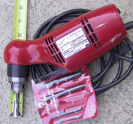
In photos, we will show the removal of the old studs, and also the tools we used for this work. 
          
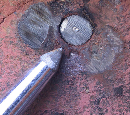
The first step is to flatten the surface at the end of the broken bolt.  Where bolts have broken, the surface is often jagged and sloped, which will cause the drill bit to wander off-center, when attempting to drill the hole.  The stud in the photo was broken just above the surface, and we used a grinder to flatten the surface at the broken stud. When a bolt is broken off below the surface of a threaded hole, a jagged break often can be flattened with punches to get a better surface for drilling.
          We used a heavy hammer and center punch to leave a “dent” for the drill to follow.  Without center punching first, it would be impossible to keep the drill in the center of the bolt. 


Before this step, we drilled a small pilot hole using a 1/8th inch drill.  (The small diameter drill is easier to keep straight and centered than a large diameter drill.)  Then we used a ¼ inch drill to finish with this 5/16inch stud.
          The drill will attempt to grab the bolt just when breaking through the backside. Typically, that’s the moment when the broken fastener will spin out of the threaded hole.  Also, when drilling through the broken bolt, vibration will help to break it free.  And drilling completely through leaves the bolt as a hollow tube, which may allow it to slightly collapse and loose some its grip at the threads.
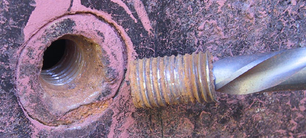
          This classic case of rust frozen fastener, shown above, came out squealing and with much powdered rust pouring from the threads.  Notice that the threads at the fastener are even galled.  Before installing a new stud we oiled the threaded hole and cleaned the threads with a tap. 
       
          
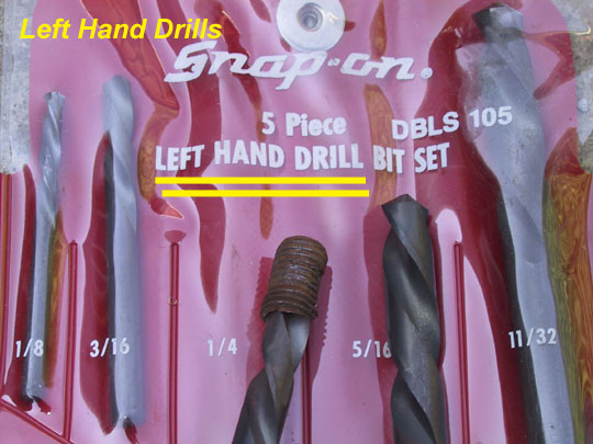
              Notice that these are LEFT-HAND drills, and they must be used with a reversible drill.  Ours are by Snap-On tools, and Snap-On offers more than one model of Left Hand drills.  Snap-On tools are typically excellent in quality, but other tool companies also make left-hand drills.  (Check with the tool dept. at Sears, or your favorite tool store.)

      The drills in the set shown above are short length High Speed Drills, and are rated for drilling in steel and other metals.
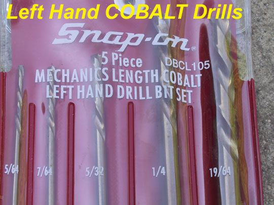
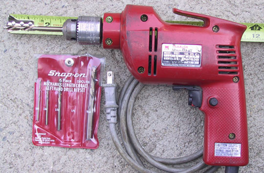
          The set shown below are COBALT, long length, left-hand drills.  The Cobalt is harder material than the standard high-speed drills, and the Cobalt drills are our choice for drilling out grade 8 bolts. 


          The short-length drills, used with an angle-head drill motor, can get into places where lack of clearance would prevent working with a long drill and typical drill motor.
  
          Sometimes the longer drill bit with typical drill motor is needed to reach down into places where the angle-head and short drills would not work.
          What ever the set-up used, the DRILL MOTOR should be powerful enough to drill at low RPM without stalling.  Smooth running, powerful, and strong even at low RPM drill motors are best suited for this work.

IMPORTANT

As with any drilling operation, watch for chips while drilling.  When making chips material is obviously being removed.  If the drill is smoking and not making chips, then stop immediately.  The drill may have to be sharpened, and probably reduce the RPM while drilling. 
          If a fastener does not come out with this left hand drill method, there are various types of “easy-out” extractors.  Or, sometimes there is opportunity to drill an over size hole and then re-thread the hole to the next size larger. Some applications can use the next size larger bolt, otherwise the “heli-coil” method can restore the threaded hole to its original size.  But, these alternative methods will require drilling first, so the left-hand drill method is never a wasted effort. 
                  
          
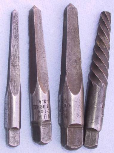
                  Two types of “EASY-OUT” extractors are shown in the photo above.  When available, the type on the right is a favorite and has been less likely to break off in the broken bolt.  But the three at the left have also been successfully used to remove broken bolts. 


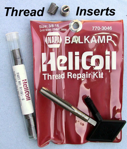
          Especially in soft aluminum, the “HeliCoil” thread repair kit is very useful.  The hardened steel thread insert actually adds strength when used in soft metals such as aluminum.  The method is to drill the proper size hole for the next size larger thread tap. Then cut new threads in the drilled hole using the tap.  And then use the tool to install the new thread insert.  The thread insert is threaded both inside and out.
        
            And always when using a thread tap, turn it in about 1/3 turn at a time, or until it begins to feel snug.  Then back it up to cut the removed material.  And then turn the tap in some more.  (Simply forcing the tap into the hole will plug the tap and not result with good threads.) 

TIP

          A stud is stronger than a bolt, especially when the threads are questionable, which sometimes is the case after struggling to remove a broken bolt from a threaded hole.  Minor damage to threads when struggling to remove the broken bolt can reduce the strength of the threads.  And then when the new bolt is tightened into place, sometimes the remaining threads will pull out.
          With correct stud installation, the stud is screwed into the threaded hole without applying pressure to the threads, and without galling the threads.  After stud installation, the part is slipped over the stud, then install the correct washer, and then tighten the nut.
          The stud is stronger because thread contact at the stud and at the threaded hole will be stationary at the time pressure is applied (when tightening the fastener).  But when a bolt is used to mount a part, the bolt is rotated in the threaded hole during tightening, which can tear out weak threads.
When installing the stud into the threaded hole, the author prefers to strengthen and anchor the stud into place with Loctite.  (Rather than double nut the stud and force it against the bottom of the drilled and threaded hole.)  The “red version of Loctite,” is preferred.  (“stud and bearing mount” purpose version, it’s the permanent version)
No doubt there will be times when clearance problems will make it impossible to use a stud, rather than a bolt.  Sometimes there is not room to slip a large part over a stud, but rather the part has to be slipped into place from the side.  (The stud gets in the way–making it impossible to slip the part into place from the side.)  But when a stud can be used rather than a bolt, the stud will result with greater fastener strength than the bolt.

II.     Apart from this the stud can also be removed by welding the bolt tip to the stud,thereby removing the welded bolt along with the broken stud by use of simple spanner.....

 III.   Another method is to making a undercut on the stud surface such that it resembles like an screw, so that it can be removed with the screw driver....

keep reading.....mail me topics you need on my blog.....

Saturday 14 July 2012

Overview of primitive and existing systems


Overview of primitive and existing systems

       Achieving the highest efficiency from a modern diesel engine depends on attaining a perfect combustion process in the cylinder each time injector fires. Various concepts have emerged with time to overcome the deficiencies of older systems and to improve upon them. Many of them have been successfully put to use. 

1.  Air- injection system:
 

The relevant fuel valve is mechanically operated. These valves consist essentially of three parts, namely a casing, a needle or mushroom valve, and an atomizer. The casing houses the needle the valve and atomizer, and forms a receptacle for the fuel charge and injection air; the valve, which is operated by a cam through a rocking lever, admits the fuel into the cylinder at a correct time; while the atomizer restricts the flow of fuel and breaks it up into small particles. The casing has two passage opening into it, the smaller from the fuel pump leading to the lower part of the casing immediately above the atomizer, and the other from the injection air bottle admits the injection air at the upper part of the casing. At the points where the fuel and injection air enter the casing small non return valves are usually provided, their object being to prevent injection air which has already passed into the fuel valve from entering the fuel pipe connecting the fuel pump and the fuel valve and causing air –lock, and also to prevent fuel from entering the injection air-pipe.
   
As a safeguard against pressures sufficient to cause damage occurring in the fuel valves, a bursting disc is provided on each valve. The functions of the atomizer are: ·         To break up the fuel into small particles

·         To cause the small particles of the fuel and injection air to mix together.

·         To regulate the rate at which the fuel enters the cylinder when the valve opens.
 

                  The fuel pump delivers exact amount of fuel, necessary to develop the required power, into the fuel valve casing every cycle, where it awaits the opening of the valve. When the valve opens, the whole of the fuel in the casing is forced into the cylinder by the injection air, the pressure of which is greater than the prevailing pressure in the cylinder. Therefore when the valve closes the casing contains only the injection air at 1000 lbs/sq in, and when the next charge of fuel is delivered into the casing it will lie on top of the uppermost atomizing ring with compressed air above and below it. Thus when the valve opens, air below the fuel charge escapes into the cylinder, and the resulting sudden reduction in pressure will cause the air above the fuel charge to begin moving towards the cylinder at a high velocity.
                                             
                  As the only way for the air to reach the cylinder is through the slots or holes, as the case may be, in the atomizing rings, it chops the fuel up in small pieces, as it were, and carries the “pieces” with it into the cylinder.
 
                       The operation of atomizing and injecting the fuel charge is comparatively gradual. The arrangement of the injector valve housing containing the fuel atomizer can clearly be seen.   
                    The fuel valve begins to open and admission of the mixture of fuel and injection air commences, irrespective of whether the engine is two stroke or four stroke type, when the crank is from 1-5 degree before the end of compression stroke, the actual point depending upon the rotational speed of the engine and the shape of the fuel cam toe-piece employed to open the valve. The object of starting injection slightly before the piston reaches the end of the combustion stroke is to ensure that the combustion process has begun immediately the piston begins its working stroke. If the combustion process is delayed until after the piston begins to move on its working stroke the thermal efficiency will be reduced. The fuel valve remains open only long enough to ensure the whole of the fuel charge being injected. If the valve remains open longer than this no harm will result, but the consumption of injection air will be much greater than it need be, and overall efficiency of the plant will be reduced, since it is not possible to regain the whole of the work expanded in compressing the air. If, on the other hand, the period the fuel valve remains open is insufficient, a little of the fuel charge will be left in the valve, each cycle, and eventually the engine will stop owing to unatomised fuel being injected into the cylinder. Such a state of affairs will result in any engine if the lift of the fuel valve is very much less than is ought to be, or if the obstruction to the flow of fuel through the atomizer is excessive.

                                     If the injection air pressure is lower than the cylinder pressure, fuel will not be injected into the cylinder and some of the hot compressed air into the cylinder will flow into the fuel valve, when the valve opens and may ignite the fuel therein, with grave consequences. Should the fuel ignite dangerous pressures may result in the fuel valve, since by the time the fuel has started to burn, the fuel valve will have closed and the burning of fuel will take place in a confined space. The injection air pressure must, therefore, never be less than about 200 lbs/sq greater than the compression pressure in the cylinder. 

                                      In all air injection engines the fuel valve closes when the crank is around 40 degree beyond the TDC, which gives the period of opening in the neighborhood of 45 degree, but the maximum lift of the valve varies according to the size of cylinder.

 1.  Airless injection system:


                                  Small land-type engines have operated on this system of fuel injection for great many years, but it was not until about 1930 that it was universally adopted for large marine engines.
  
                                                                                                                                   
                                                                                                                              Prior to this the air injection engine could burn a wide range of distilled fuel and achieve a higher break mean pressure in the cylinders, even though its mechanical efficiency was lower by some 8%, due to the power required to drive the air compressor. This superiority over the airless injection system resulted from two factors, the first being the supercharging effect of the injection air which increased the available oxygen by about 5%, and secondly the action of the air in promoting turbulence, and consequently better mixing, of the atomized fuel and air.
     
Technical improvements in the fuel pumps and fuel valves of airless injection systems have eliminated the advantages possessed by the air-injection system, and has shown the former system to be no less superior on all grades of fuel commonly used.

Now that it is usual to employ the heaviest grade of boiler fuel, which must be heated to obtain the desired degree of atomization, the absence of injection air is an advantage, because in expanding down from 1000-5000 psi the resulting refrigerant effect would tend to cool the fuel as it entered the cylinder.

Airless injection system consists of two broad categories:

a)    Common rail injection system

b)   Jerk type injection system


A. Common rail injection system:

It has one or more high pressure multiple plunger fuel pumps. Fuel is discharged in to a manifold or rail, which is maintained at a very high pressure. Sufficient volume capacity is provided in the high-pressure pipeline by pump and accumulator bottle, which serves to decrease the pressure fluctuation at quick load changes. The metering and timing of fuel injection is controlled by mechanically operated fuel valves in the earlier types of engine and by the timing valves in the later type of engines like P&J type of Doxford engine. This timing valve times and meters the fuel injection in the combustion chamber. The valve is operated by camshaft the duration of opening of timing valve and hence the period of injection of fuel in the cylinder regulates the quantity of fuel admission.

B. Jerk type injection system:

It can be broadly classified into two categories

I.      Port controlled

II.    Valve controlled
                                                                                                                       
             
·        Port controlled fuel pump ( BOSCH  type)

Undoubtedly the most popular system used on board today consists of the BOSCH type Reciprocating pump of the kind shown in the Fig. feeding fuel  into high-pressure pipeline, which leads directly to the fuel injector v/v.

                             Essentially the pumping element is a robust sleeve or barrel, which envelops a close fitting plunger. In its implicit form the barrel has a supply part at one side and a spill port at the other side. The fuel cam through a roller follower actuates the plunger. As soon as the rising plunger covers the supply and spill ports, the fuel is pressurized and displaced through the delivery valves towards the injectors. A sharp pressure wave is generated which runs through the high pressure piping to the injector causing the injector valve to open and inject. As soon as a relieved area on the plunger uncovers the spill port, the injection ceases. The relief on the plunger has a helical control edge so that rotation of the plunger by means of the control rod varies the lift of the plunger during which the spill port is closed and therefore the fuel quantity injected and the load carried by the engine.
                              
                                                                                                                       
In the figure shown above it can be seen how some special modifications to the conventional BOSCH type pump makes the unit more reliable.

This injection pump contains the following features:
·         The mono element design is a rigid and distortion-free solution even at high injection pressures.

·         A constant pressure relief valve eliminates the risk of cavitation erosion by maintaining a residual pressure, which is on a safe level over the whole operating field.

·         A drained and sealed-off compartment between the pump and the tappet prevents leakage fuel from mixing with lubricating oil.

·         Precaliberated pumps are interchangeable.

This design however suffers from a number of deficiencies:

§  The pressure pulses can easily runback and forth between the pump and injector several times before the injector is actually forced to open and inject. Thus, it becomes very much essential for the operator to ensure that the system is in excellent condition and to ensure that the fuel is properly treated and free of dirt. If, for example, nozzle spray holes are partially blocked by extraneous elements or carbon particles, the pressure wave may not be sufficiently reduced within the system. This eventually results in destruction of fuel pump cam or other vital parts of the injection system upon the next stroke.

§  When the spill port opens and a pressure upto 1600 bar is released, cavitation and/or erosion is likely to occur, affecting both the housing directly opposite the port, and the plunger land which is still exposed to the port at the instant of release.

§  There is also the effect of dilution due to pressure, the need for lubrication, and the need to prevent fuel from migrating into spaces where it could mingle with crankcase oil.


·        Valve controlled fuel pump:
                                                                                               
     Fig. (1.4) Shows a simple schematic diagram of operational and the fuel metering device of a valve control type fuel pump which has both end control of fuel injection. Normally these pumps are built together in pair. The pump barrel is completely filled with fuel under positive pressure during the downward stroke of the plunger. The pressure of the supply fuel oil opening the suction valve as the plunger performs its return stroke and later part of stroke commences filling of the pump barrel by push rod lifting the suction valve further. The injection of fuel begins only after the plunger has advanced further in its stroke when the suction valve is seated. The injection of fuel begins only after the plunger has advanced further in its stroke when the suction is seated. The delivery is continued till it is terminated by the spill valve lifted mechanically near the end of the plunger stroke. The time of opening of spill valve or closing of suction valve depends on the engine load and is variable by regulating mechanism. Delivery takes place through the spring loaded discharge valve. Fine adjustment of opening or closing of spill or suction valve is done by adjusting screw fitted on push rod. Therefor both end control of fuel injection is achieved with this type of pump very easily. Fuel pumps are provided with pneumatic safety mechanism that shuts of the fuel to the engine if the speed of the crankshaft exceeds the permitted maximum. To protect the fuel pump housing against excess pressure there is a safety valve provided which opens at a preset pressure of 900 bar.
                                                                                                                                      

     The safety valve is always enclosed in housing so that in case of the valve opening the fuel is drained to fuel oil leakage tank. When HFO is being used, the pre-heated oil must be circulated before the engine is started.  When the engine is being reversed the camshaft and thus all the fuel cams are turned relative to the crankshaft in such a way that fuel injection takes place at the correct timing for both ahead and astern operation.


 Comparison of the two systems


#


Common rail injection


Jerk type injection

1
All the pumps deliver to a common pipe called common rail or manifold. The system pressure at around 400-550 bar.
Pumps deliver to individual cylinder, fuel injector or injectors. Pump discharge pressure can go upto 1300 bar even.
2
Since it involves only common manifold, so any leakage or damage to this pipe will lead to engine stoppage till the defect is rectified.
Its respective pump drives each cylinder unit so any defect or failure only leads to particular unit suspension and other units would be working normally.
3
Required power for driving pumps is normal and its around 2% of the total power developed in the engine.
Required power for driving pumps is around 6% of power developed in the engine.
4
Eccentric runs drive pump assembly and hence it is very smooth and noiseless.
This is very noisy due to sudden pressure rise caused by the stiff cam profile on the pump plunger.
5
If a single pump in the system malfunctions, then that can be cut down from the system and the capacity of the other pump can be increased to adjust the defective pump output so that the overall output of the engine remains same.
Since pumps deliver to individual units, any malfunctioning of a pump cuts off supply to that particular unit resulting in engine power loss.
6
Cams on the timing valve assembly(as in Doxford Engine) are symmetrical in relation to the overall engine output remains same.
Ahead and astern running are timed differently. The firing order is different.
7
Pressure in the common rail is relatively lower; hence is less efficient.
High pressure ensures greater penetration and better atomization.
8
Runs with least stress in the gearing system and consumes less power from the engine.
Imparts more stresses on the gearing system; hence consumes more power from engine.
9
Has valve related problem (timing valve); hence more maintenance is required.
Fuel pump has only are discharged valve; hence maintenance requirement and related problems is less.